Page 8.922
Basic WWII IFR Aircraft Control
Return to whittsflying
Return to IFR Contents
.OUTLINE OF BASIC INSTRUMENT FLYING SYLLABUS;
...WWII AIR FORCE 10 IFR
COMMANDMENTS; ...Pilot error
50 years ago; ...An 80-year Old Joke;
.
As an IFR rated pilot, you will never regret reading this material
Notes are from a WWII Instrument Instructor who was in poor health and would pay for the plane while I learned to fly from the right seat in 1969. He gave me the following, contained in a 4 by 5 inch 38-page booklet which served as the basic IFR training manual in WWII. The capital letters are 1/16" Very thin paper had the pages printed so that two pages were glued to the corresponding pages front to back. Pages 20 and 21 in the middle of the book were glued back to back by pages 19 and 22. Only one staple holds the booklet together. A rather unusual construction to say the least. Italicized parts have been noted by Jay for my special attention along with his remarks in quotes. I never really had an opportunity to give him proper credits or thanks for his help.
This is the way I initially learned IFR flying. It was while spending
two post-war months in Link Trainers on Tinian Island. I had to wait that
long for a troop ship to take me back to the States. Twenty-five years
later, when I first took flying lessons it all came back to me. My instructor had to keep telling me to look outside over the nose instead of at
the instruments.
Gene-
"If your students can consistently perform under these standards, they will be Top Notch Basic Instrument Pilots. Best Wishes", Jay
Editorial Note: I have 'spell-checked the booklet but have left the
original grammar, structure, punctuation and spelling . The size of print I have
used is Times New Roman (9). It is more than twice the size of the print used in
the booklet. There have been some interesting changes in terminology shown
below:
Artificial Horizon(A/H) = Attitude Indicator (AI)
Directional Gyro(D/G) = Heading indicator (H/I)
Let-down = Approach
Pull-up = go-around
Miles per hour instead of knots
Constant let-down vs stabilized approach
Use of covered cockpit vs foggles or hood
Rate group vs partial panel
Emphasis on IFR takeoffs
Stick vs Yoke
Unusual positions vs unusual attitudes
Belly landing vs wheels-up
Wheel lever vs gear switch
Working area vs practice area
A student pilot of WWII might have said:,
I was preparing the aircraft for a flight to the working area where my
instructor planned a series of unusual position exercises using the covered
cockpit. This is more difficult than contact flight. By having the
caged artificial horizon and directional gyro covered I would have to fly
without the venturi system, using the stick and rate group from liftoff to
letdown. I rather expect to a establish a constant mph let-down and to do
a pull-up or even a belly landing if I forgot the wheel lever. We will use
the interphone to communicate as when he gives me the emergency wheel procedure
which includes checking the hydraulic pressure.
After starting the engine I must uncage the flight indicator and observe the
horizon precess slowly to level at which time I set the little airplane. I
must remember to check it for tipping over when turning of the ground and again
after five minutes. I will also wait five minutes after uncaging the
directional gyro before setting it with the compass and setting it again on the
runway.
Once in the air I will use the airspeed meter to note change of speed and set the trim tabs as required. Stick and rudder are held in a relaxed manner and moves with pressures rather than movement. My instructor is supposed to demonstrate control movements before I am to try.
It might be of interest to know that the shape of the holding pattern used today was created because earlier gyroscopic instruments needed the straight sides to prevent precession.
(Pages -1- and -2- blank for notes)
OUTLINE OF BASIC INSTRUMENT FLYING SYLLABUS
Printed at Headquarters Army Air Forces Western Flying
Training Command
Santa Ana, California
Preflight Familiarization and Discussion
__________
COCKPIT LAYOUT
Seat student in the aircraft and point out to him the location of all controls and accessories including the location of the throttle, mixture control, pitch control, carburetor heal adjustment, landing gear and flap controls, fuel tank selector valve, trimming tabs, radio switches, seat and rudder pedal adjustments, coupe top emergency release, operation of the instrument hood, control locking devices, light switches, manual hydraulic pump, and any other controls or accessories in both cockpits.
Discussion--
1. Fuel system including a discussion on supply carried and the fuel consumption
per hour and the range of the aircraft.
2. Vacuum pump and venturi system.
3. Pitot-static system and how it affects the instruments concerned.
4. Alternate source.
5. Caging and uncaging of gyro instruments.
Dust filters on the instruments.
7. Use of radio and interphone.
8. Acknowledgement of aircraft control.
Page -3-
9. Engine operation and desired instrument readings.
10. Use of carburetor heat and how it affects the mixture.
11. Emergency wheel procedure.
12. Normal take-off cockpit check.
H--hydraulic pressure and system functioning.
T--trimmed for take-off.
M--mixture rich.
P--full low pitch.
Fuel--sufficient amount for flight and full tank.
Flaps--up
Carburetor Heat--cold.
13. Cockpit check of the necessary instruments prior to any night or
instrument flight.
a. Flight indicator.
1. Uncage after engine is started.
2. Horizon bar should precess downward slowly and remain absolutely level.
3. Adjust little airplane
4. Allow motor to run 5 minutes to attain proper speed, then check the
horizon bar for any tendency to tip over while
making turns on the ground.
b. Directional gyro
1. Uncage after engine is started.
2. Rotor speed is attained in 5 minutes
3. Uncage with a sharp twist of the caging knob, it should remain steady.
4. Set with magnetic compass and recheck with compass in takeoff position.
c. Turn and bank indicator
1. While taxiing aircraft, make left and right turn, needle should be
positive in its indication and not sluggish. See that
ball is free in the ball race.
d. Suction Gauge
1. Proper suction of 3.5" Hg to 4.5 Hg.
Page -4-
e. Altimeter
1. Set to Station Altimeter setting and it should then read the
elevation of the field. If it doesn't, note the scale error.
2. Tap face of instrument and reset if necessary.
f. Vertical speed indicator
1. Adjust if possible
.
g. Air speed indicator
1. Pitot tube cover removed
2. Pitot heat on in any kind of precipitation or icing weather.
3. Check ammeter for current flow when heat is turned on.
h. Compass
1. Adequate fluid.
2. Accuracy of headings--check with runway headings.
3. Compass card free and should swing while taxiing.
i. Carburetor heat
1. Always check if sufficient carburetor heat is available. Apply
full heat on engine runup.
Page-5-
LESSON 1
Object--Familiarize student with airplane, the flight instruments and
demonstrate the reactions and indications of these instruments to
changes of attitude.
DEMONSTRATIONS--
1. Initial cockpit check of the instruments.
2. Contact flight demonstration of the aircraft's flying characteristics.
3. Relation of the artificial horizon to the true horizon.
4. Caging and uncaging of the artificial horizon in flight.
5. Control of attitude in the pitching plane with A/H and the altimeter.
6. Control of attitude in pitching plane with airspeed, altimeter, and power
settings.
7. Control pressure instead of actual movement. Over-controlling and
relaxation.
8. Acceleration and deceleration in relation to the airspeed meter.
9. Use of trim tabs.
10. Unreliability of vertical speed indicator.
OUTLINE OF THE FLIGHT--
1. Student does cockpit check of the instruments and repeats it to instructor
over the interphone.
2. With the hood open, the instructor takes off and proceeds to
demonstrate the flight characteristics of the aircraft, stressing mainly the
amount of control pressures necessary to produce the desired maneuver.
Instructor demonstrates feel of controls, mild rolling aileron movements,
effectiveness of trim tabs, straight and level flight at various speeds
pointing out the uses of the elevators and throttles and the various changes
of attitude during such. Also stalls and effects of the flaps should be
covered briefly
Page-6-
3. The student is given control and allowed to go through above maneuvers. The instructor speaks through the interphone and explains to him what to notice.
4. Instructor takes control and does a series of gentle banks, climbs, and
glides and tells pupil to note indications of the artificial horizon and
compare it with the true horizon.
Point out the following:
a. Looking at aircraft from the rear;
b. Instantaneous indications, no lag.
c. Approximation of attitude.
d. Small movements of little aircraft correspond to large movements of real
aircraft. Tends to lead student to over-control.
5. The student is given control and is allowed to demonstrate the above points to himself. At all times drawing a comparison to the true horizon.
6. Instructor takes control and does a few shallow and steep banked turns
calling the student's attention to the pointer scale that indicates the
angle of bank. Point out absence of pitching scale.
7. Instructor has pupil cage the gyro horizon then puts aircraft to steep bank and has pupil uncage the instrument. Returns to level flight and note tilt of horizon bar. Caution. Should always be level when the instrument is uncaged.
8. Instructor has pupil cage the gyro horizon then uncage it only one-third
of the way. The aircraft is banked and it is noticed that the instrument
becomes inoperative when a very shallow angle of bank is reached. Caution:
Instrument should always be fully uncaged.
9. Instructor retains control and proceeds to demonstrate use of horizon to
hold a constant attitude as necessary in holding a constant climb or level
flight or a descent. Caution: Safety of the aircraft in a climb or in
level flight does not depend solely on maintaining the exact climbing or level
flight attitude, but depends on airspeed and the attitude must be
varied to hold the desired airspeed.
Page-7-
10. Demonstrate that for a given power setting, the airspeed determines the correct attitude for the desired condition of flight.
11. Demonstrate that for a given airspeed, the power setting determines the condition of flight, whether it be climb, descent, or level flight. Emphasize: The airspeed is held constant by varying the attitude slightly on the A/H. With the airspeed being held constant, the amount of power determines the condition of flight. High airspeed and low power, a descent; low airspeed and high power, a climb; level flight airspeed and level flight power setting will result in level flight. Demonstrate level flight at various airspeeds and power settings.
12. Give student control and have him fly level using the A/H and the altimeter cross-checking on the airspeed. Level flight at various speeds.
13. Student retains control and flies level by airspeed and altimeter alone. Horizon caged.
14. Instructor takes control and demonstrates the apparent lag in the airspeed indicator. From level flight put aircraft in climbing attitude. Note that airspeed does not immediately indicate climbing airspeed. Due to the aircraft's momentum, it takes time to decelerate. Lag is not in the airspeed indicator. Return to level flight. Note that airspeed does not indicate level flight airspeed. It takes time to accelerate due to inertia. This factor is very important when using the airspeed indicator to make changes of attitude. The trend or the rate of change of airspeed gives an indication as to how sharp a change of attitude is made.
Page -8-
15. Instructor demonstrates that elevators control airspeed and throttles control rate of ascent or descent. Fly level and close throttle, airspeed falls off very slowly. Fly level, pull back stick, airspeed falls off fast, ease stick ahead, airspeed builds up fast. Emphasize: Elevators control airspeed and throttles control climb or descent.
16. Demonstrate the excessive lag in the vertical speed meter (Use as a trend indicator.) Student note A/H as the nose is quickly raised; there is a short pause before the vertical seed indicator indicates that you are climbing although you are diving.
17. Demonstrate effect of torque with change of throttle setting or change of airspeed. First with throttle setting constant, lower nose and increase speed, note that the nose yaws to the right. Decrease speed and note the nose yaws to the left. Now hold airspeed constant and then decrease power. This has the same effect as increasing the airspeed i.e., the nose yaws to the right. Decrease speed and note the nose yaws to the left. Now hold airspeed constant and then decrease power. This has the same effect as increasing the airspeed i. e., the nose yaws to the right. Now open the throttle and note that the nose yaws to the left. Emphasize that when increasing speed or when reducing the power, left rudder trim is needed. When the speed is reduced and the power setting remains constant or if power is added, right rudder trim is applied.
18. Student is given control and flies level, using horizon, altimeter, and airspeed. On return to the field, the student is given a few constant airspeed descents..
19. Instructor lands the aircraft and a discussion of the flight takes place
Page-9-
LESSON II
Object--To review Lesson 1 with and without hood. Practice climbs and
descents with constant airspeed and varied power settings. (under
hood). Teach climb, level flight at various speeds, and proper use of trim
controls.
DEMONSTRATIONS--
1. Any demonstrations necessary to clear up Lesson I.
2. Proper method of climbing aircraft.
3. Leveling off from climbs.
OUTLINE OF FLIGHT--
1. Student repeats instrument check to the instructor over the
interphone.
2. Instructor takes off with the student observing the instruments with
the hood open. Climbs to altitude and levels off.
3. Student is given control with the hood open and is made to fly level
first with the altimeter and A/H then with the altimeter and airspeed, then
with all three of these instruments.
4. The hood is now closed and the student is made to repeat these methods
of level flight under the hood. No emphasis is placed on direction, however,
the wings must be kept level.
5. Student remains under hood and the instructor handles the throttle and
the student maintains level flight by reference to the airspeed, altimeter,
and A/H.
6. Student now is given the throttle and is made to fly level at slow
speeds, medium speeds, and high speeds. Stress the use of the altimeter and
A/H when making the changes of airspeed. If reducing speed, close the
throttle and hold attitude constant, and check on the altimeter.
Page-10-
As the altitude starts to fall off, raise the nose of the A/H in order to hold the altitude constant. When the desired airspeed is reached open the throttle to the power setting necessary to maintain level flight at that speed. CAUTION: Vertical accelerations for very small changes of attitude in high speed aircraft are so great that the vertical speed meter cannot be used in maintaining level flight. Altimeter can be used much better. In slower aircraft, the trend of the movement of the vertical speed is used to give an idea which way the altimeter will move.
7. The instructor leaves the student under the hood and proceeds to teach him climbing. Important things are safe airspeed and if obstacles are to be cleared a high rate of climb is desired. Assume the approximate climbing attitude. Hold this attitude constant until the airspeed remains constant, then make the necessary changes in attitude to make the final adjustment of the airspeed. The amount of power applied will determine the rate of climb. Stress the proper use of trim when entering the climb.
8. Give the student an exercise as follows: Climb 500 feet then level off
for a few minutes followed by another climb for 500 feet. Student holds
constant airspeed and reduces throttle to produce descent. Start previous
exercise over again. When leveling off from a climb, leave on climbing
power, and as desired altitude is reached, lower the nose of the A/H to hold
this altitude allowing the airspeed to build up gradually.
9. Student does constant airspeed descent back to airport.
10. Instructor lands and a critique on the student's work is given.
Page -11-
LESSON III
Object---Review climbing and level flight and to teach turns and straight
flight.
DEMONSTRATIONS--
1. Demonstration of proper way to turn aircraft.
2. Demonstration of aileron drag.
3. Demonstrate how correction for a slip or skid will alter the rate
of turn or angle of bank.
4. Demonstration of straight flight.
OUTLINE OF FLIGHT--
1. Student repeats instrument check to the instructor.
2. Instructor takes off with student under the hood observing the instruments. Student is given control after climbing attitude and airspeed is attained.
3. Student climbs the aircraft and levels off at 500 feet intervals with periods of level flight between climbs.
4. Student reviews level flight at various speeds and climbs at various rates of climb.
5. The hood is opened and turning is taken up. The instructor takes control and places feet on floor and instructs student to do same. Aileron is applied and student is told to notice that the aircraft starts a turn almost immediately as the bank is applied. Recall student's attention, that this is exactly as was learned in Ground School. Emphasize that if aircraft is properly trimmed, turning means banking, especially in large or fast aircraft. Even if the aircraft is turned with rudder alone one wing is speeded up increasing its lift, and causes the aircraft to bank. Demonstrate a turn with aileron alone and demonstrate a turn with aileron alone, pointing out the faults in each. Demonstrate aileron drag and explain why rudder is needed on entries and recoveries from turns to overcome aileron drag.
Page -12-
6. The instructor retains control and demonstrates the instrument indications in a turn. As bank is applied, it will be noticed that the A/.H indicates such, the ball indicates whether or not the rudder is used to properly counteract aileron drag, the turn needle indicates a turn and the directional gyro shows you are turning. Demonstrate how easy it is to turn by using the A/H to hold a constant bank and the altimeter and A/H together to hold altitude in the turn.
7. Explain the proper way to fly turn needle. It indicates the rate at which the nose moves around the horizon. In a normal coordinated turn, the rate of turn indicated by the needle depends upon the angle of bank. A constant angle of bank means a constant rate of turn. A steep bank means a fast rate of turn, a shallow bank, a slow rate of turn. Emphasize: The airplane flies on instruments exactly as it does on contact and the turn needle should be flown as such. If the rate of turn is too great, take off bank; but at the same time aileron is applied to shallow out the bank, rudder must be coordinated to overcome aileron drag. This is a common fault in flying the turn needle, in turns and in level flight. Aileron is used to keep it centered or at the desired position and as the aileron is used, due to aileron drag, the turn needle momentarily moves in the opposite direction. Angle of bank is given directly by the A/H and indirectly by the turn needle.
8. Demonstrate skidding turn and a slipping turn and explain that they are caused by improper rudder trim or by tensing up on the rudder pedals. Demonstrate when the skid is corrected by centering the ball with rudder, it also slows up the rate of turn and the bank must be increased slightly to hold the desired rate of turn. The opposite is true in a slipping turn.
9. Student is given control with the hood open and is made to do turns of 20 degrees bank and reversals
Page -13-
and concentrate particularly on smooth coordination of stick and rudder and the use of the elevators to hold altitude constant in the turn and during the reversal. Next have him do these turns with particular emphasis on the instruments. First on the horizon and altimeter then with the turn needle airspeed and altimeter.
10. Instructor takes control and demonstrates the Directional Gyro by doing a series of turns and point out how accurately it points out the heading of the aircraft while compass does not read true due to northerly and southerly turning errors, land acceleration and deceleration errors. Explain that the Directional Gyro must be set with the magnetic compass and reset every so often.
11. Instructor demonstrates straight flight. First, on the Directional Gyro, then with the turn needle and the compass. It will be explained that when straight flight is being done, causes for any unintentional deviation from this is usually caused by improper rudder or aileron trim or unconscious pressures on the controls applied by the pilot when tense.
12. Student is placed under the hood and is given control and made to fly level and practice turns on the A/H and turn needle using the A/H as a means of holding a standard rate turn. Also straight and level flight is practiced. Student does constant airspeed descent on return to airdrome.
Page -14-
LESSON IV
Object--Review straight and level flight, turns and climbs. Teach descents a
given rate.
DEMONSTRATIONS--
1, Any demonstrations necessary to clear up points already covered.
2. The proper way to do a descent.
OUTLINE OF FLIGHT--
1. Student gives instrument check to instructor over the interphone system.
2. Instructor takes off with student under the hood observing the
instruments.
3. When climbing attitude and airspeed are attained student is given control
and made to climb and level off at 500 foot intervals.
4. Review everything covered thus far, stressing accuracy in holding
altitude, airspeed and heading. Review straight and level flight at various
airspeeds turns (20 degree back turns on horizon and standard rate turns on
turn needle) change of speed, and climbs.
IMPORTANT: Do not slight work on the rate instruments. Let the student
fly the above maneuvers on the full panel until he is reasonably proficient.
Waste no further time on the full panel. Put him on the above maneuvers with
the A/H and D/G caged.
5. With the gyro instruments cages, have student climb with a constant
power setting and make speed changes from 110 to 100 mph and from 110 to 120
mph and then back to 110 mph. Notice the rate of climb in each case. Also
closely check to see that student is not chasing airspeed. For instance, if
he is reducing
Page -15-
airspeed, see that he makes change of attitude and then wait for airspeed
to decelerate. In making this change of attitude without the A/H, have him
try to visualize the nose of the aircraft and to note the trend of the
airspeed indicator to see how sharp a change of attitude is made.
6. Have student hold airspeed constant and climb at various rates of
climb---300 fpm, 500 fpm, and 1000 fpm. Emphasize constant airspeed and use
of power to determine rate of climb. CAUTION: Watch over-controlling; airspeed
is the master instrument when the horizon is caged
or inoperative and any changes during the climb must be corrected for
immediately.
7. Next open the hood and uncage gyros and demonstrate descents at a
given rate. The steps in teaching a descent are as follows:
a. Reduce airspeed to descending speed by closing throttle to descending
power, or lower.
b. Hold altitude constant by gradually raising the nose on the A/H as the
altitude starts to fall off.
c. As airspeed reaches proper value, gradually ease stick ahead to hold
airspeed constant and establish rate of descent.
d. Airspeed in the descent is held constant the same as in a climb, i.e.
by small changes of attitude.
e. Use small changes of power to hold vertical speed at desired position.
IMPORTANT: Do not chase vertical speed. Hold
airspeed very constant and make changes of power as necessary to obtain rate
of descent. Due to lag of vertical speed meter, the change of descent will
not take place immediately as the power is varied. Do not become impatient.
f. The vertical speed meter is good only in smooth air. To do a descent
in rough air, a given airspeed and power setting should be used to assure
the rate of descent. The rate can be checked by the clock and altimeter.
Page -16-
8. Show student how to level off from a descent. First leveling off
and maintaining the descending airspeed and level flight. Hold the rate of
descent and airspeed constant until about 50 feet above desired altitude then
open the throttle to setting necessary to check the descent and at the same
time the nose is raised slightly to hold airspeed constant when the power is
added.
Next, leveling off at cruising airspeed. While descending at slow airspeed
to level off at cruising speed, when about 100 feet above desired altitude,
add excess power above normal cruising power, at the same time holding la
slightly nose low attitude; forward pressure on the stick is necessary. Level
off at desired altitude and by this time cruising speed should have been
reached. Trim.
9. Place student under hood and make him do letdowns at a given rate, with
particular emphasis on first:
a. Speed reduction while holding altitude.
b. Holding exact airspeed while making adjustments of power. This will
necessitate small changes of attitude.
c. Appreciate the lag in the vertical speed meter.
d. Proper trimming prior to descending.
10. Student does a series of turns, interspersed with periods of level flight, climbs, and descents. Gradually work way back to field.
11. Instructor lands and critique is held.
Page -17-
LESSON V
Object--To teach turns to definite headings, climbing and descending turns,
40 degree banked turns.
DEMONSTRATIONS--
1. Turns to headings using D/G.
2. Descending and climbing turns
OUTLINE OF FLIGHT--
1. Student gives instrument check to instructor through interphone.
2. Instructor takes off with student under hood, observing mainly D/G
while on ground and as aircraft is airborne his attention should shift to
the A/H land the airspeed.
3. Student is given control, climbs to working altitude, and levels off.
4. Review previous lessons.
5. Student is then taught to do 40 degree banked turns. Emphasize holding the pitching attitude constant by referring to the A/H when rolling into turn. Then, when correct bank is reached, hold bank constant and cross check on altimeter. It will be necessary to hold a greater amount of back pressure than when in shallow banked turns. CAUTION: In holding attitude, do not over-control the little airplane on the A/H.
6. Student is taught to turn to definite gyro headings. Stress to start recovery from turn slightly in advance of the heading. The amount of lead depending on the angle of bank or the rate of turn.
7. Student is next taught climbing and descending.
a. To teach climbing turns, have student put aircraft in climbing attitude and attain climbing airspeed and
trim the aircraft. Then roll into the turn from the climb.
Page -18-
b. Important to hold constant airspeed and constant angle
of bank and rate of turn.
c. In teaching descending turns have student obtain the
descending airspeed and rate of descent, then enter turn. CAUTION: More
power must be added in climbing and gliding turns at constant airspeed due
to the increased drag (aileron drag) in the turn. If power is not
added, and airspeed is maintained, the rate of climb will fall off or the
rate of descent will increase.
d. Closely check airspeed in descending turns and take
care not to let angle of bank or rate of turn get too steep.
8. When the student is proficient on these, have him roll into turn and climb or turn and descend at the same time.
9. Review all phases.
10 Return to field and hold critique.
Page -19-
LESSON VI
Object-- To show all the errors and uses of the magnetic compass. To show
time turns and any other demonstrations necessary.
DEMONSTRATIONS--
1. Northerly and Southerly turn error.
2. Acceleration and deceleration error.
3. Use of the Directional Gyro.
4. Turns to headings with compass alone.
5. Time turns.
OUTLINE OF FLIGHT--
1. Student gives cockpit check to instructor over interphone.
2. Student under hood, observing the instruments while instructor demonstrates instrument takeoff.
3. Student is given control and practices climbing turns with emphasis on constant airspeed and constant rate of turn.
4. Student next levels off at working altitude and reviews straight and level flight at various airspeeds.
5. Student retains control and practices descents at given rattails, and descending turns followed by climbs at a given rate and climbing turns.
6. The hood is opened and the instructor takes control and demonstrates
the northerly turning error of magnetic compass:
a. Line aircraft on magnetic north.
b. Start turn to west.
c. Note compass indicates turn to east.
d. Return to north and start turn onto east and note that the opposite is
true. Also line up on north, then start a turn, very gradual, to either east or west and note that the compass will indicate that
you are still flying straight on north. (D/G will indicate a turn, mag comp
will not.)
Page -20-
7. Instructor demonstrates southerly turning error.
a. Line aircraft up on magnetic south then start turn to east.
b. Note that compass indicates turn in proper direction but indicates
that the rate of turn is much faster than it actually is.
c. Return to south and demonstrate same thing on turn to west.
8. Instructor demonstrates the acceleration and deceleration errors
of the magnetic compass.
NOTE: These errors are noticed only when flying an easterly or westerly
direction.
a. Line up aircraft on magnetic east at a constant airspeed.
b. Raise nose and reduce speed.
c. Note that although heading remains the same, the compass indicates
turn to the north.
d. Return to constant airspeed, then lower nose and note that compass
indicates a turn to the north.
e. Turn onto west and show that the same is true.
f. Demonstrate the above by making speed changes with throttle instead of
elevator.
9. Instructor explains that when setting Directional Gyro to the magnetic compass or when using the magnetic compass alone, the airspeed should be kept constant and the turn needle and ball should be kept constant and the turn needle and ball should be centered, so that the magnetic compass gives an accurate indication.
10. Instructor demonstrates turns to headings by compass and turn needle alone. Important: This system of turns to headings can only be used in smooth air, and is a short cut to turns onto cardinal headings only. CAUTION: Will not be accurate if the angle of bank exceeds 15 degrees, or a standard rate turn is exceeded.
Page -21-
a. Turn to north by holding above mentioned rate of turn and when
compass reads 30 degrees short of north, roll out and keep turn needle
centered. Compass settles down on north.
b. Turn onto south by holding a standard rate turn and when magnetic
compass passes by south and settles down 30 degrees past south, roll out of
turn and center turn needle. Compass reads approximately south.
c. Turn onto east or west from the south. Note compass very accurate. When
exactly on east or west, stop the turn.
d. Turn onto east or west from the north. Note that the compass lags
behind, then catches up suddenly.
e. CAUTION: In these turns, particularly when turning to the east or west,
hold airspeed steady, and if turning to north or south, keep the rate of turn
constant.
11. Demonstrate time turns.
12. With the hood open allow the student to have control and go over the above demonstrations himself.
13. Close the hood and make student practice turns by compass alone and by timing.
14. Return to field and hold critique.
Page -22-
LESSON VII
Object-- To teach Pattern A on the full panel and the rate instruments. To
teach steep turns with and without the Artificial Horizon.
DEMONSTRATIONS--
1. Demonstrate pattern "A"
2. Demonstrate 50 and 60 degree banked turns with the A/H.
3. Demonstrate two and three needle width turns on turn and bank indicator.
OUTLINE OF FLIGHT
1. Student repeats instrument check to instructor through the interphone.
2. Instructor takes off with the student under the hood observing the instruments.
3. Student is given control and climb to working altitude. Practice climbs at varying airspeeds and power settings. Also practice climbing turns.
4. Instructor takes control:
a. Opens hood and teaches the student to do Pattern "A"
on the full panel.
b. Pattern 'A' is demonstrated on the rate instruments, using time
turns for all the turns.
5. Student is given control with hood closed, and is made to practice the pattern with and without the gyro instruments caged.
6. At this point let student review let-down turns at no particular rate of descent.
7. Instructor takes control and with the hood open demonstrates a steep turn with the full panel.
-23-
Emphasize:
a. Watch. A/H on the entry and keep nose of little airplane
exactly on horizon; roll into turn smoothly.
b. Advance throttle if necessary.
c. Increase back pressure necessary according to the degree of
bank.
d. When in turn it may be necessary to hold nose of little
airplane slightly above horizon bar.
e. Cross check on altimeter.
(Dangerous disorientation-vertigo and high speed stalls.)
f. CAUTION: Steep turns are not normal
during instrument flying, and are for practice only.
In fast aircraft (250 mph or over),
standard rate turns (single needle width) should be avoided as they entail
a steep bank at such high speeds. A half rate turn should be used.
8. Instructor retains control and demonstrates a steep turn without the use
of the A/H.
IMPORTANT: When entering a steep turn on instruments without the use of
the A/Hl, it is very important to note the airspeed prior to starting the
turn. When a steep bank is reached, it is possible for the nose to drop to a
very nose low attitude before the altimeter will start to indicate a loss of
altitude, whereas, the airspeed would start to increase as the nose started
down. On entry into the turn looking at turn needle, and as soon as it
passes the standard rate mark, cross-check very closely on the airspeed and
immediately as it starts to increase come back smoothly on the stick. Once
in the turn, the airspeed will read 5 to 20 mph slower than the level flight
airspeed, even though throttle is added. The amount of speed lost in a steep
turn is dependent on the power added and the angle of bank.
In flying the airspeed in a steep turn, remember that it required a hard pull to raise the nose to reduce airspeed, and a very light release of pressure will lower the nose. Hold rate of turn constant with aileron and rudder.
CAUTION; Never "Horse back" on the stick, danger of high speed stall resulting. Never let angle of bank increase when changing pitch angle of aircraft, danger of over-banking resulting in a spiral dive.
9. Work student back to the field, land and hold critique on the lesson.
Page -24-Page -25-
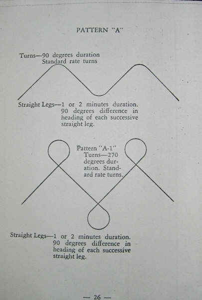
PATTERN "A" Turns--90 duration standard rate turns
Straight Legs--1 or 2 minutes duration. 90 degrees difference in heading of
each successive straight leg.
Pattern "A-1" --Turns--270 degrees duration. Standard rate turns.
Straight legs --1 or 2 minutes durati0n. 90 degrees difference in heading
of each successive straight leg.
-26-
LESSON V111
Object-- To teach instrument takeoff and Pattern "B" on full panel,
and on rate instruments.
DEMONSTRATIONS--
1. Instrument takeoff.
2. Pattern "B"
OUTLINE OF FLIGHT--
1. Student gives cockpit check of instruments to the instructor.
2. Instructor lines aircraft directional gryo to nearest five degrees of
the runway heading.
3. With the hood open the student will do the first takeoff.
Emphasize:
a. Eyes on directional gyro as long as aircraft is on the ground.
b. Open throttle slowly at first to eliminate as much torque as
possible.
c. Quick easy movements of the rudder to control heading. If
heading varies more than a few degrees, aircraft will run off
runway.
d. Keep stick centered and make no effort to raise tail. If it
comes up of its own accord that is all right.
e. When aircraft feels light or starts to skip, make an effort to get it
off. Ease back stick and as aircraft leaves the ground,
focus eyes on the A/H and hold attitude in exactly the same position as
was previously memorized on ground, with the wings
level.
Page -27-
f. After a few seconds lower the little airplane very slightly
to normal climbing attitude and cross-check with airspeed and turn
needle. Maintain direction during the climb.
g. After the initial climb is underway and will not distract
attention from flying instruments, raise the undercarriage and change
engine power and rpm to climbing.
h. Caution that after takeoff, do not try to obtain climbing airspeed
immediately. The aircraft will leave the ground at about 65
to 75 mph, and a drastic change of attitude will result in
flying back into the ground. Hold attitude on A/H constant as you leave the ground, then gradually lower it and keep the airspeed slowly
building up to climbing value.
4. Instructor takes control and lands the aircraft.
5. Student is placed under the hood and repeats instrument takeoffs until he acquires a degree of safety and accuracy.
6. After student is reasonably proficient have him continue to a climb from takeoff and practice climbing turns to the working altitude.
7. Instructor demonstrates Pattern "B" with student under hood.
8. Student takes control and practices Pattern "B". (Illustration on page -32-)
9. Instructor lands aircraft and critique is held.
Page-28-
LESSON IX
Objects--Let-downs to predetermined altitudes and headings. Unusual
positions. Pattern "B".
POINTS TO BE DEMONSTRATED--
1. Let-downs to predetermined altitudes and headings.
2. Unusual positions.
OUTLINE OF FLIGHT--
1. Student gives cockpit check of instruments to instructor.
2. Instructor lines ship up with runway; student makes instrument takeoff.
3. Student continues to climb after takeoff, practicing climbing turns,
stressing
a. Safe climbing airspeed.
b. Constant angle of bank (rate of turn)
c. Proper trim.
4. Instructor takes over, explains let-down into predetermined altitudes
and headings. For instance, let-down from 4000 feet to
3500 feet, at the same time turn from East to West. Should get to new
heading at the same time.
IMPORTANT: Factors governing correctly executed turns of this kind.
a. Must hold exact airspeed.
b. Must hold standard rate turn.
c. Must give vertical speed time to settle down.
Steps in doing Maneuver:
a. Holding heading, reduce airspeed from cruising to descending.
1..Cross-check Altimeter for altitud
2. Airspeed for correct airspeed
3. D/G for heading
Page -29-
b. When descending airspeed reached, lower nose and go into bank simultaneously, opening throttle slightly to give proper rate of descent.
c. If rate of descent is off--correct with throttle; if airspeed is off--correct with elevators.
d. During turn, check D/G with altimeter. If descent is at rate of 500 fpm when 90 degrees of turn have been completed, altitude should have been reduced by 250 feet.
e. Vary rate of descent or rate of turn to correct if altitude and amount of turn do not coincide.
5. Student flying, practice let-down in predetermined headings and altitudes, full panel, and on rate group alone.
6. Discussing unusual positions:
Instructor flying, student watches instruments during recoveries.
Causes for unusual positions:
a. Carelessness.
b. Excessively turbulent air.
c. Flying alternately contact and instruments.
Accidentally getting into unusual positions, spirals and spins are usually
the result.
(Very
dangerous--Make up your mind either VFR or IFR) In
Spiral:
Indications: Airspeed building up, two or three
needle width turn indicated.
Recovery:
a. Disregard gyro instruments.
b. Center turn needle by coordinating controls.
c. Ease back on stick to reduce airspeed. Yanking back will cause high
speed stall. As soon as A/S begins to
fall off, release pressure on stick to prevent stall.
Page -30-
Spin:
Indications: Stick probably all the way back, airspeed not building up
appreciably, slip-skid indicator off to opposite side as turn needle.
Recovery:
1. Normal N. A. C. A. spin recovery.
IMPORTANT: The idea is to recover to normal level flight and
if a course was being maintained at a definite altitude, recover from the unusual position and return to the original course and altitude. Airspeed
and turn needle are the main instruments used on recovery.
a. Retard throttle on high speed dives.
b. Watch the airspeed. It is building up, execute normal spiral recovery. Rule:
Airspeed must be gotten first
and slowed down last. Once turn needle is centered, keep
it that way until airspeed is normal. (Needle Ball
Airspeed is the MANTRA.).
Give
student at least three spins recoveries. The N. A. C. A. method of recovery
is advisable on AT-6 and BT-13 aircraft.
7. As soon as student understands these ideas, put hood up, and let student
recover from following:
a. Diving spiral.
b. Top of wing-over; airspeed will pick up.
c. Start of wing-over, nose high at high airspeed.
d. Nose high spiral.
e. Complete stall.
f. Steep slip--steep bank with top rudder.
g. Pick up speed in diving spiral, ease nose up at high speed, remaining in
spiral.
8. Return to field with series of let-downs and gliding turns.
9. Instructor land ship and hold critique.
Jay's Note: "Airspeed - MASTER Instrument, however safe flight can be accomplished if airspeed (indicator) is out. PANIC is the killer. Rely on TRAINING ONLY.
-31-
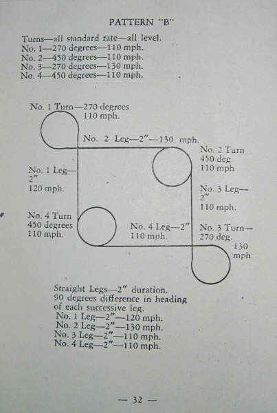
PATTERN "B"
Turns -- all standard rate -- all level
No. 1 -- 270 degrees --110 mph
No. 2 -- 450 degrees --110 mph
No. 3 -- 270 degrees --130 mph
No. 4 -- 450 degrees -- 110 mph
No. 1 turn -- 270 degrees
110 mph
No. 2 Leg-- 2" -- 130 mph.
No. 2 Turn 450 deg
No. 1 Leg 2". 110 mph
No. 3 Leg 2" 120 mph
Climb 1000' 110 mph
No. 4 turn No. 4 Leg--2" .
Lose 2000' Climb 1000'
110 mph . 4 . 110 mph .
No. 3 Turn 270 deg 130 mph Level
3 Straight Legs -- 2" duration.
90 degrees difference in heading of each successive leg.
No. 1 Leg -- 2" -- 120 mph.
No. 2 Leg -- 2" -- 130 mph
No. 3 Leg -- 2" -- 110 mph
No. 4 Leg -- 2" -- 110 mph
-32-
LESSON X
Object -- General review on the following:
1. Pattern "A", "A-1", and "B".
a. On full panel.
b. On rate group .(Needle, Ball Airspeed)
2. Instrument takeoffs.
3. Descending turns to predetermined altitudes and headings.
4. Pull-ups from let-downs
5. Unusual positions and recoveries
6. Demonstrate Pattern "C". (See page 37)
Page -33-
LESSON XI
Object -- Final check on Basic Air Work
OUTLINE OF FLIGHT
1. Student takeoff under hood.
2. Proceed to working area:
a. Straight climbs.
b. Climbing turns
3. Pattern "A" on rate group.
Limits -- 100' in altitude.
10 seconds timing
10 mph in airspeed.
4. Pattern "B-1" on full panel.
Limits -- 80' in altitude
8 seconds in timing
5. Unusual positions.
Grade on:
a. Recovery on given heading.
b. Speed and smoothness of recovery.
6. Let-downs and pull-ups at definite altitudes.
7. Return to base at constant let-down.
Emergency Wheel Procedure for AT-6 and BC-1.
Two conditions arise
1. Wheels will not go down at all or only go partially down.
2 Wheels will go down but not lock.
Remedy for first condition is to note the hydraulic pressure when the time-lag lever is pushed down. If no pressure registers, in all probabilities the engine hydraulic pump is broken. Next try using the hand auxiliary pump. If no pressure can be built up with this, there is probably a failure in one of the hydraulic lines. Under these conditions if the aircraft is skidded sharply from side to side with rudder,
Page -34-
centrifugal force will throw the wheels outwards and into the locked position. Normally the wheels will fall down and lock by gravity alone. However, on some aircraft due to lack of lubrication or tight bearing fits, they will only come down part way by gravity and if no hydraulic pressure is available, the above procedure is recommended.
If the wheels will not come down at all or only come down a very short way, it is advisable to dive the aircraft and make a sharp pull out. At the time of the out the wheel lever should be in the down position and the time-lag lever as well as the hand pump should be employed at the moment of the pull-out. If they will not come down, there only one thing to do. Fully retract them if possible, call the control tower and make a belly landing on the grass portion of the field.
There is one exception to the above. Sometimes when operating off a wet slushy field under near freezing conditions, the water and slush will collect on the locking pin and after the wheels retract, they will freeze the pins that lock them up. If this is the case, try and find a warm strata of air to fly in and possibly melt off the ice. As a means of prevention, avoid taxiing through slush or large puddles of water, secondly leave the wheels down after take off until the water and slush blow off or freeze. Then the ice will crack and break off the locking pins when the wheels are retracted.
If any of the above methods fail to bring the wheels down, a belly landing is unavoidable.]
The remedy for the second condition is as follows. If the wheels are not quite fully down and the hydraulic pressure is insufficient, try skidding with rudder as previously mentioned. If the wheels go fully down and the horn still blows it may be that the locking pin spring is broken or the pin is jammed with dirt or ice. Under these conditions, the procedure for forcing the locking pin in place manually is undertaken. This is done by putting the undercarriage lever ahead in the emergency travel portion.
Page -35-
If the horn still blows and you are not positive of the position of your wheels, fully retract them and make a belly landing.
A case sometimes arises where the wheels will not fully retract after takeo9ff. They practically will always come up most of the way, but quite often they will not retract the remaining distance into the wheel well. This is due to the oleo shock absorber being stiff. As the aircraft leaves the ground, the wheels normally will drop a few inches as there is no weight on them to compress the oleo leg. If the oleo leg is stiff, as the aircraft leaves the ground, it will not extend as the weight is taken off it. The "V" type unit on the strut which purpose is to keep the wheel aligned with the strut which purpose is to keep the wheel aligned with the longitudinal axis, is then in the compressed position and when the wheels are retracted, this "V" will catch on the ledge of the wheel well and not allow the wheel to fully retract.
A remedy for this is to lower the wheels then pull up sharply so centrifugal force will extend the oleo leg and stretch out the "V" type, wheel aligning device, then the wheels should retract satisfactorily.
ANGLE OF BANK IN RELATION TO AIRSPEED FOR STANDARD RATE TURNS
Use this angle of bank chart to get bank angles for
speeds in the patterns.
Airspeed Angle of Bank
Miles Knots Degrees
90 78.3 12
100 87.0 13.5
110 95.7 15.0
120 104.4 16.0
130 113.1 17.5
140 121.8 18.5
150 130.5 20.0
160
21.0
170
22.5
180
23.5
190
24.5
200
26.0
Page -36-
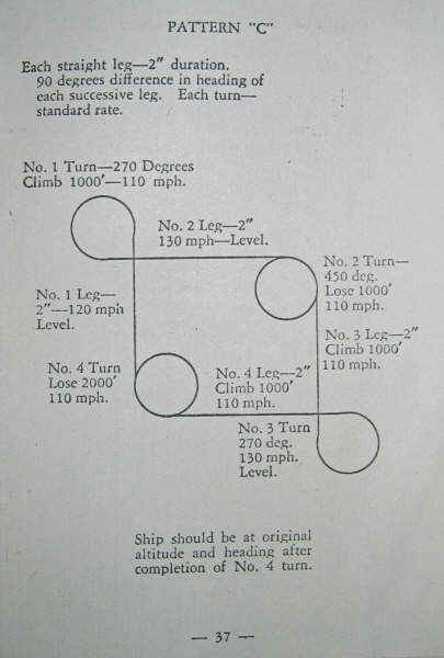
PATTERN "C"
No. 1 Leg No. 1 turn -- Outside 270 degrees Climb 1000' -- 110 mph
(15 degree bank)
No. 2 Leg-- 2" -- 130 mph - Level. No. 2 Inside Turn
450 deg Lose 2000'
No. 3 Leg . 2" 110 mph No. 3 Outside Turn
270 deg 130 mph - level
No. 4 Leg 110 mph 2" . Lose 1000' 120 mph Level
No. 4 turn Inside 450 deg Climb 1000' 2"
110 mph
Ship should be at original altitude and heading after completion of No. 4 turn.
Page-37-
FUEL CAPACITY AND CONSUMPTION
BT-13A
Capacity: 120 gallons
Consumption 25 gallons per hour
AT-6
Capacity 178 gallons
Consumption 28.5 gallons per hour
AT-6Cl
Capacity 110 gallons
Consumption 28 gallons per hour
BC-1
Capacity 110 gallons
Consumption 28 gallons per hour
BC-1-A
Capacity 178 gallons
Consumption 28 gallons per hour
Page -38-
WWII AIR FORCE 10 IFR
COMMANDMENTS
--Follow the indications of thy instruments and verily thee airplane will
follow along, even as the tail follows the sheep.
--Do not stick out thy neck a foot; stay within the confines of thy ability and
thou shalt live to a happy old age.
--Know the appointed words and approved methods, so that if thy neck dropeth
out, thou shalt be able even unto thyself to place same in it's proper place,
upon thy shoulders.
--Follow thy radio beam, for these ways are happy ways and will lead to the
promised landing.
--Listen carefully, yea verily, to the signal impinging on thy eardrum, for
sometimes they seem to have the tongues of snakes and will cross up thy
orientation to the sad state to where thou must ask Heaven Herself for guidance.
(If you have never flown the radio range that existed in the 30s and 40s you
won't appreciate this advice.)
--Assume not, neither shalt thou guess, that thy position is such, but prove to
thine own satisfaction that such is the case. Let not the weapons of poor
judgment or over-confidence fly you to hell.
--Boast not, neither brag, for surely Old Devil Overcast shalt write such words
in his book and thou shalt some day be called for an accounting.
--Trust not thy seat (of thy pants), but follow thine instruments. Read and
truly interpret the word as given from thine instrument board and know that the
responsibility lies not with the hand that rocks the control column, but in and
with the mind that directs the hand, and thou shalt be blessed with a long and
happy life.
Pilot error
50 years ago
In December of 1947 an Air Force study released the following
analysis of pilot errors that precipitate accidents. There is
no reason to think things have changed since then.
50% of problems are "substitution" errors where the
incorrect control is moved
18% are "forgetting" errors in which the pilot forgot
to unlock, check or use a control.
18% are "adjustment" errors by operating a control
too slowly, rapidly or into the wrong position.
5% are unintentional activation.
6% were "reversal" errors such as moving the control
in the wrong direction.
3% are caused by inability to reach a control.
An 80-year Old Joke
An 80-year-old man went to the doctor for a checkup and the doctor was
amazed at what good shape the guy was in. The doctor asked, "To what do
you attribute your good health?"
The old timer said, "I'm a pilot and that's why I'm in such good shape.
I'm up well before daylight and out flying up and down the countryside."
The doctor asked, "How old was your dad when he died?"
The old timer said, "Who said my dad's dead?"
The doctor said, "You mean you're 80 years old and your dad's still
alive? How old is he?"
The old timer said, "He's 100 years old and, in fact, he flew next to me
this morning in his own airplane. That's why he's still alive; he's a
pilot!"
The doctor said, "Well, that's great, but I'm sure there's more to it.
How about your dad's dad? How old was he when he died?"
The old timer said, "Who said my grandpa's dead?"
The doctor said, "You mean you're 80 years old and your grandfather's
still living! How old is he?
The old timer said, "He's 118 years old."
The doctor was getting frustrated at this point and said, "I guess he
went flying with you this morning too?"
The old timer said, "No, Grandpa couldn't go this morning because he got
married."
The Doctor said in amazement, "Got married!! Why would a 118-year-old guy
want to get married?"
The old timer said, "Who said he wanted to?
Return to whittsflying
Return to IFR Contents
Next 9.94 WWII
Supersonic Trainer